Faema Special smart espresso machine
I figured I’d do a write-up on the conversion of my Faema Special S87 into a “smart” espresso machine. I put quotes around the word “smart” just because in common parlance today, that just means “WiFi connected”, as in your “smart lamp” or “smart outlet”. This machine is now WiFi connected, however, it has been enhanced more than just being able to turn it on and off from my Amazon Echo Dot.
As with any project, I had started this off with a QFD matrix, and here is the list of features I was looking to implement eventually (in no particular order, asterisk indicates required feature):
- Boiler water level control*
- Dispense espresso*
- Boiler temperature regulation
- Volumetric dispensing
- Automatic backflush
- Maintenance counters
- Part lifetime tracking
- Auto purge HX
- LCD display
- HX temperature regulation
- Scheduled power on/off
- Pre-infusion
- WiFi
- Automatic descale
- Clock
- Shot timer
Espresso Electronics v1
The first version that I decided to make based on the cost of hardware, sensing equipment and actuators necessary will manage the boiler level and boiler heater (with boiler level control), dispensing espresso, maintenance counters with part lifetime tracking and WiFi interface. The WiFi interface can allow for reading and writing data from the microcontroller, such as the maintenance counters, and can also take the place of scheduling power on and off as well as maintaining time of day awareness and synchronization. This base set of functionality doesn’t require any additional sensing (like flow meters and pressure sensors) or an LCD. A simple UI can be accomplished just using momentary buttons with integrated LED indicator. Additionally, with minimal equipment a lot of additional features can be added via software.
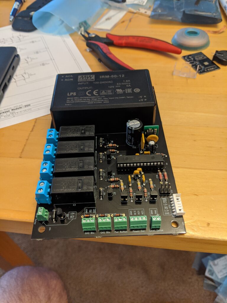
Here is the prototype, with basic working functions:
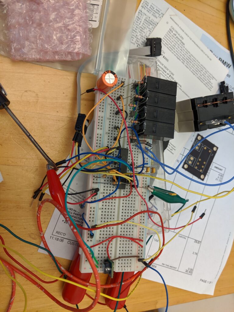
The requirements for this initial version are simply that there be an output stage (driver and relay) for the pump, boiler fill valve, heating element and the two grouphead three-way valves. The largest draw of the smaller relays is the pump at a maximum of 4A at 240VAC, however I selected 10A relays, and an off-board 20A 240VAC relay was selected for the heating element which can draw up to 17A. They’re driven by NPN transistors with a transient suppression diode across the relay coil. The circuit diagrams are below.
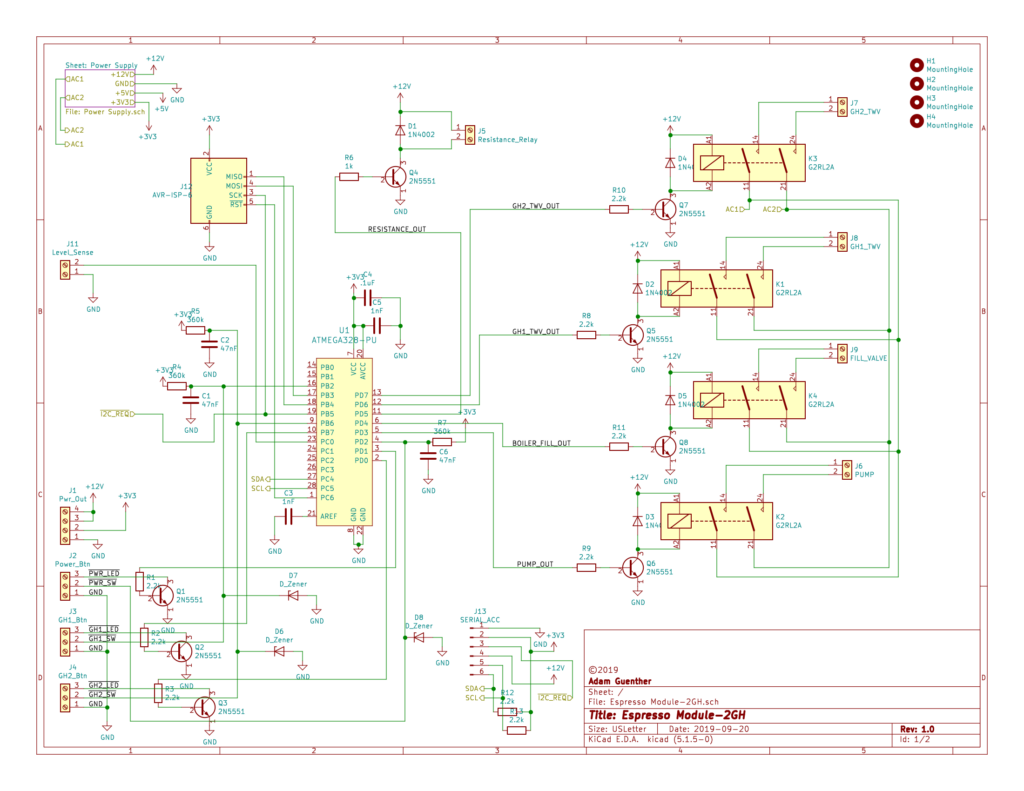
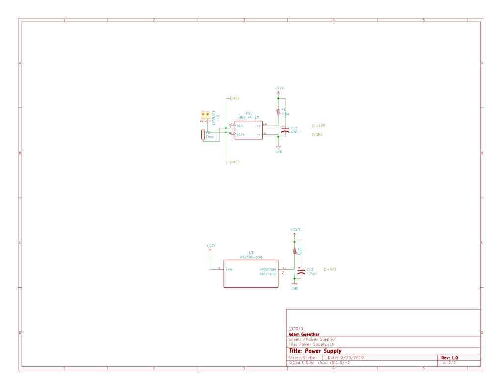
You can see it is a relatively simple design. My choice to use the premade AC-DC converter simplifies it and adds a bit of cost, however I think the Mean Well IRM-45-12 is a tremendous value considering that it has a very flexible voltage input range of 85VAC-300VAC and outputs 12V at 45W. This is more than enough power to supply all the relays and microcontroller as well as a WiFi controller and two LCD screens should I want to add them later, and allows this controller to work in 120V machines, 240V machines and almost any combination of international power standards. Since this is just the first generation prototype, I think spending the $16 for this switching power supply well worth it, however this might be costly if it were to be mass produced.
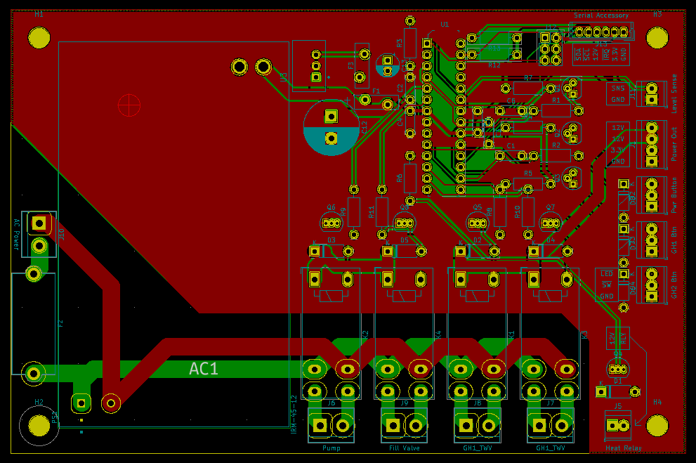
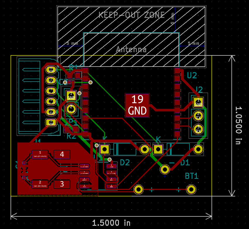
I designed the PCB, keeping the 240VAC parts separate from the digital circuits and also trying to lay things out on the board such that when installed the machine, there isn’t a lot of interference between digital and power wires as well.
I had this produced for me at pcbs.io and I thought it was a great value for the high quality boards that I received. It ended up being about $80 for 5 each of the mainboard and the WiFi accessory board. What I received was a very nice quality board:
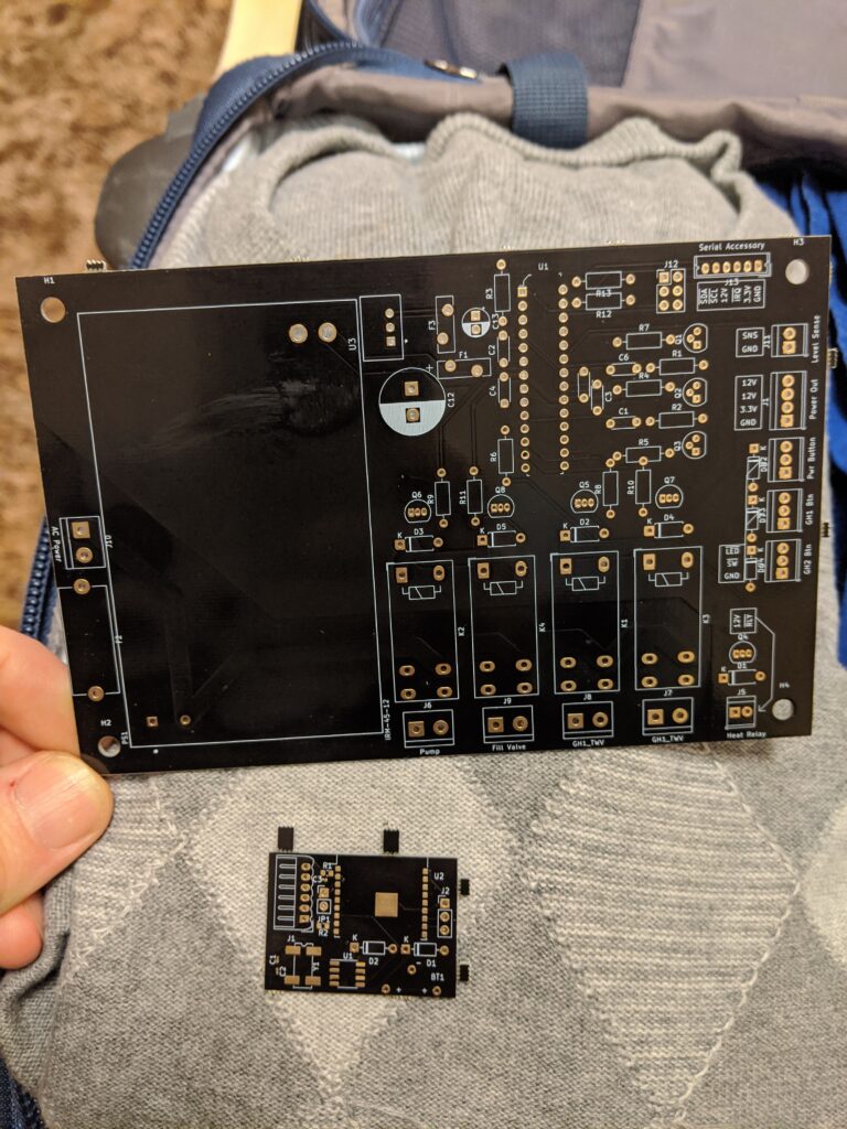
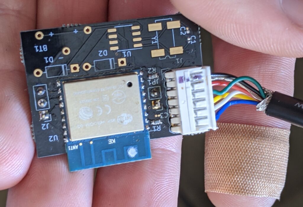
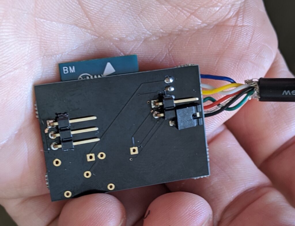
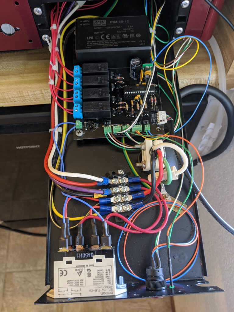
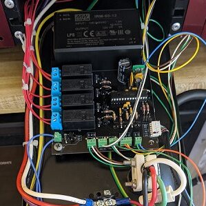
So, does it work? Yes, it works amazingly well! I’ve added the WiFi accessory board (not in the picture but I will upload later as it’s not as easy to see in the machine).
What I’d do differently
So, a couple of lessons for me:
- The RC debounce circuits on the buttons are not correct in my schematic, an oversight on my part. I’ll debounce in software for now and fix in the next version.
- I’d use optocouplers for any external inputs and outputs like the buttons and LEDs. I attached my oscilloscope to an open wire (antenna) and you can get a transient spike of up to 40V when a grouphead valve snaps closed. For now, I’ve managed this using a 4.8V reverse biased diode, but it’s hard to find something that clamps just above 3.3V. Despite this I’ve had no issues with stability.
Machine controller software
The software in the main controller is a basic state machine running in the main loop. It was programmed in C, using Atmel Studio for Windows and the AVR gcc compiler. The buttons are tied to interrupts that toggle some values in a machine state structure and allow the main loop’s state machine to make appropriate state changes based on that. The three-wire-interface serial bus (also known as I2C) is handled via an interrupt routine that stores commands in a command buffer and then sends out from a send buffer, reading and modifying RAM, Flash and EEPROM structures and is completely self contained. When the machine is powered off (as in not operating, but still powered), the AVR goes to shutdown mode and the whole setup consumes about 1.5mA. Any of the TWI and button interrupts will wake it up, but it’ll resume shutdown when its finished processing serial data, or will stay awake if turned on.
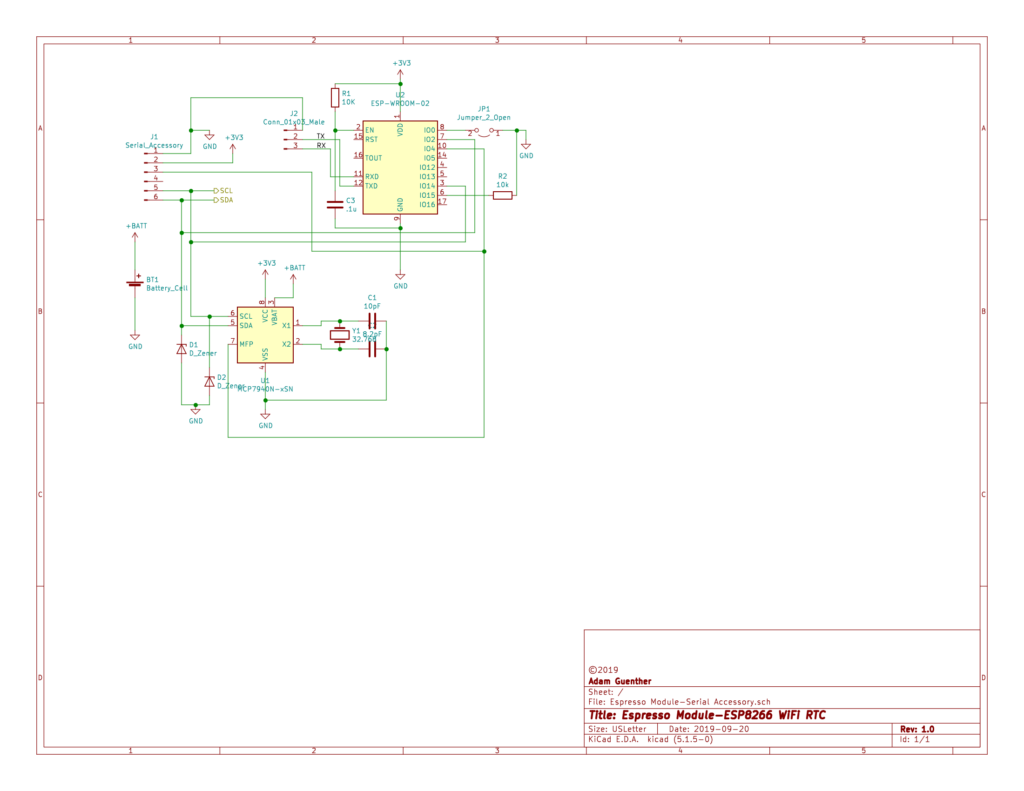
WiFi controller software
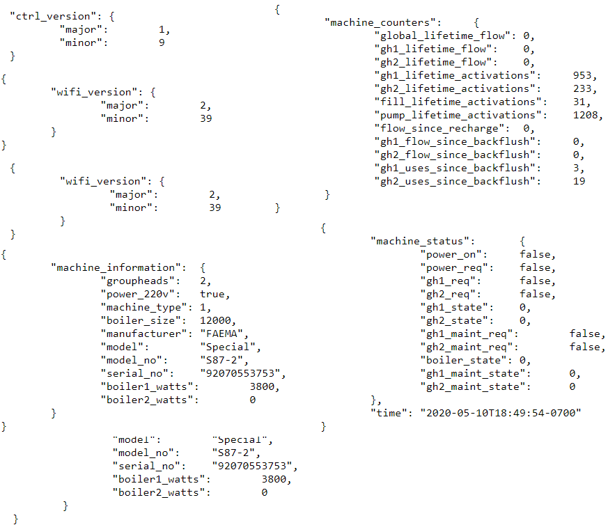
The WiFi controller is an ESP8266 and also programmed in C using the ESP8266 RTOS environment and the xtensa compiler for UNIX (MacOS in this case). The environment consists of WiFi setup using an external mobile device app (the ESP-NOW app) to set up the WiFi SSID initially, and then a bunch of WiFi endpoints. Currently there is an endpoint to read data and to write data. The device will query the machine status (power, all states of relays, LEDs, etc), maintenance counters, espresso machine information (purely informational) and software versions (for both the machine controller and the WiFi controller) as well as read and update a few WiFi controller non-volatile settings like NTP servers, update URL and timezone. Everything it returns is a JSON object, like the below examples.
Videos
Here are some videos of the machine working and demonstrations of the features:
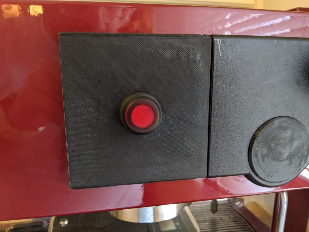
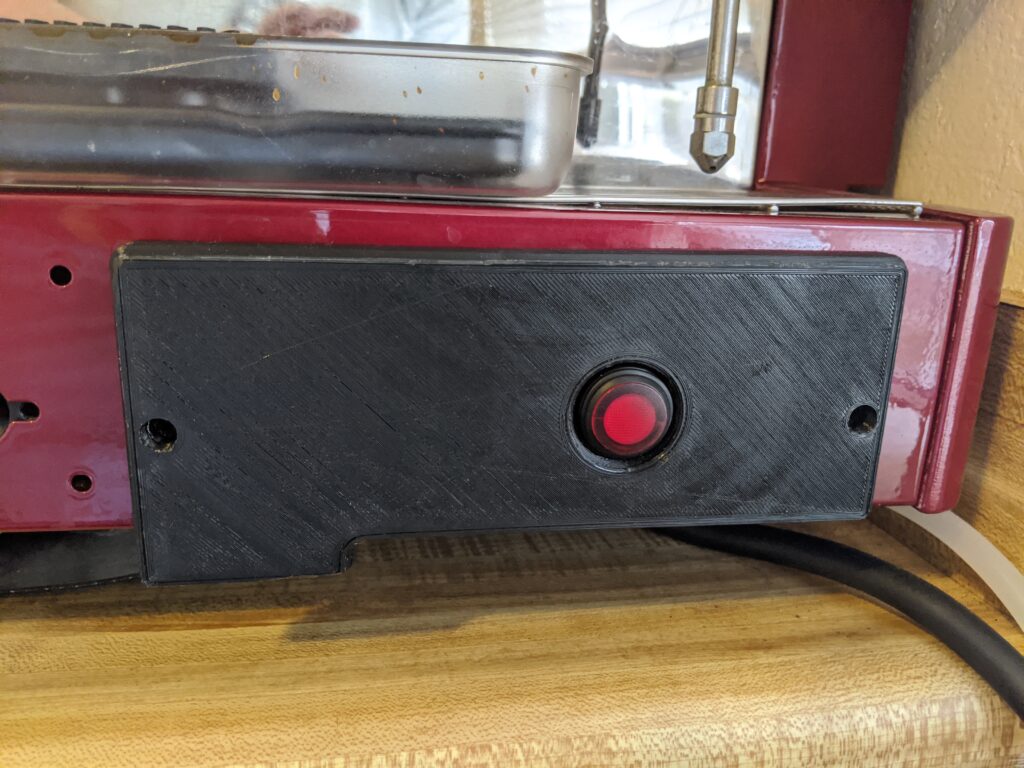
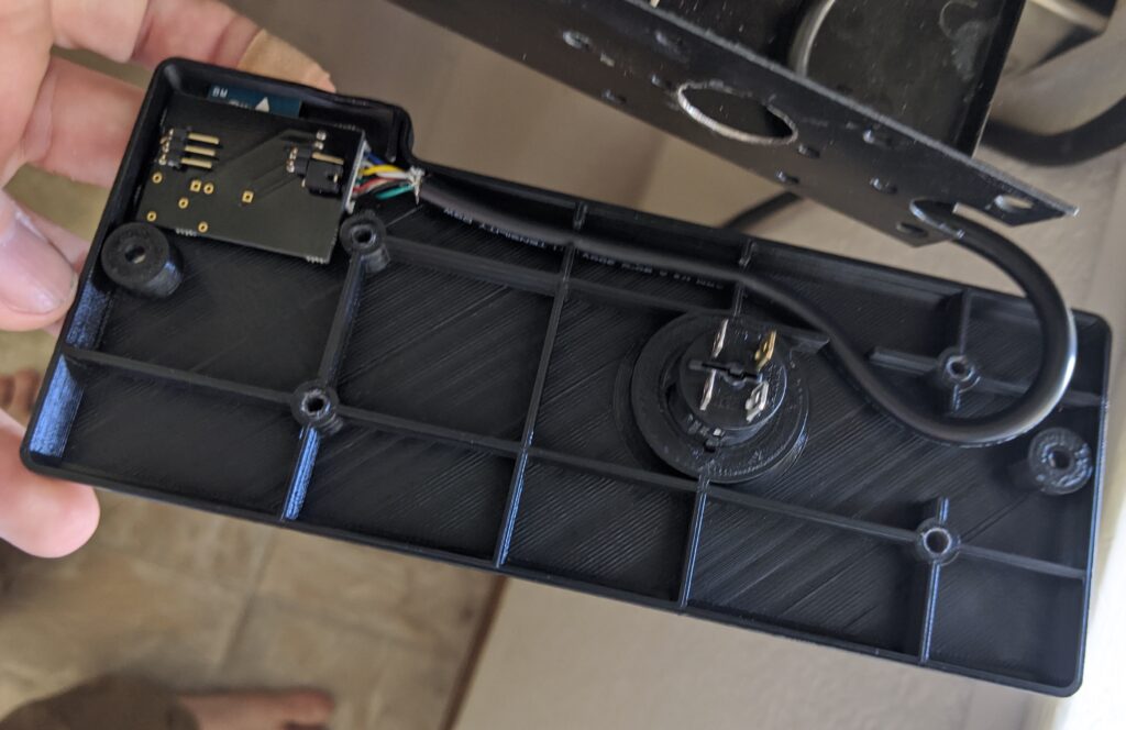
3D printed fascia panels
Some changes needed to be made to accommodate the new switches on the machine that went with the new electronics. The below pieces I’ve designed to fit the machines original mounting holes and 3D printed (mostly out of PETG for it’s durability).
Thanks for reading! I applaud you for making it this far! I hope in the future to publish a list of all the software changes, including some internal optimizations I’ve made like using the watchdog timer instead of one of the standard AVR counters, CRCs and the EEPROM wear leveling (extends EEPROM life to ~550 years, because why not?) that I’ve done.